Use bindings to update properties or property fields of one node with the properties or property fields of other nodes. Bindings allow nodes to automatically update the values of their properties in response to the changing property values in other nodes or the occurrence of some external event.
Bind the rotation property field of a node to a property to create a gauge needle which you can control with property. See Tutorial: Create gauges.
Bind the rotation property field of a node to the Scroll Position of a Scroll View node to rotate the node using swiping gestures. See Tutorial: Rotate a 3D model.
You can create bindings after you add the Bindings property to a node. Blue type marks the properties that are controlled by a binding. The properties you bind override the properties set in the Properties.
When creating bindings, keep in mind that:
Only bindings to similar data types are valid. For example, you can bind only color to color, vector2 to vector2, and so on.
Binding takes the value of the last expression, whether it is an assignment, unary or binary operation, or just a constant value or variable itself.
In bindings you can cast strings between the four fundamental types: integer, float, boolean, and string. Casts between integer and float are implicit and depend on the type of the property that uses the value. Casts to and from string are explicit.
For a list of error messages and their explanations in the Binding Argument Editor, see Troubleshooting bindings.
Creating simple bindings
The simplest of bindings bind a property of a node to one of its own properties. You can also use bindings operators and functions to modify the result, and add several bindings to the same node.
To create simple bindings:
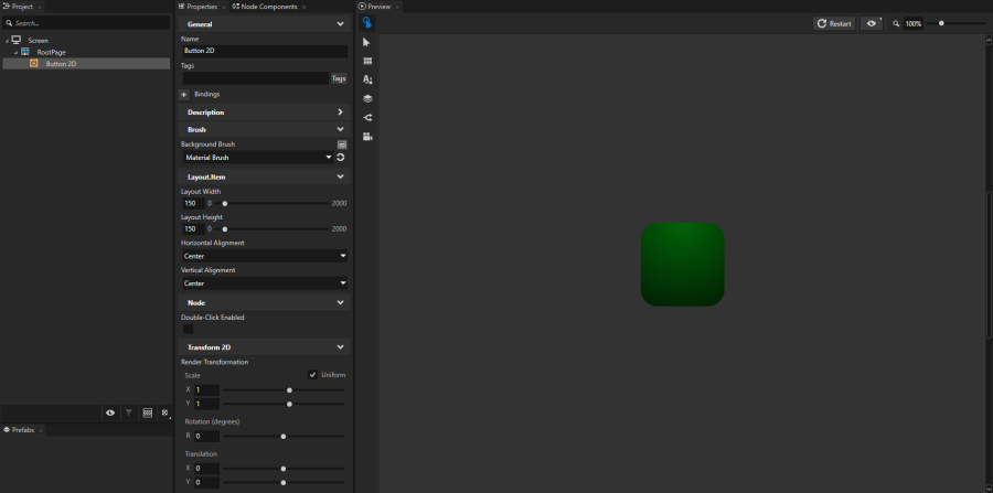
In the Project create or select the node the properties of which you want to bind. For example, create a Button 2D node and in the Properties add and set:
Background Brush to a Color Brush, Texture Brush, or Material Brush that you use to fill the Button 2D node. See Adjusting the appearance of 2D nodes.
Horizontal Alignment and Vertical Alignment to Center
Layout Width and Layout Height to set the size of the button
Render Transformation You use this property later in this procedure to set the position of the button.
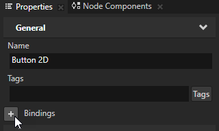
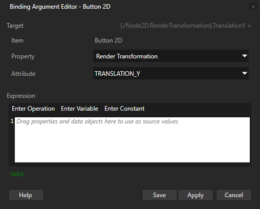
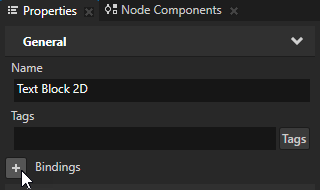
In the Properties add the Bindings property and in the Binding Argument Editor set:
Property to the property you want to bind For example, to bind one of the Render Transformation property fields, select Render Transformation.
Attribute to the property field you want to bind For example, to bind the translation property field on the y axis, select Translation Y.
In the Expression editor enter the binding expression. For example:
To bind the location on the y axis to the location on the x axis of this same node, enter:
{@./Node2D.RenderTransformation}.TranslationX
Click Apply to apply the binding. When you move the node on the x axis by changing the value of the Render Transformation property Translation X property field, the node moves the same distance on the y axis.
To bind the Translation Y property field to half of the absolute value of the Translation X property field of this same node, enter:
Click Apply to apply the binding. When you move the node on the x axis by changing the value of the Render Transformation property Translation X property field, the node moves half of that distance down the y axis.
TIP
You can apply a binding in these ways:
To apply a binding without closing the Binding Argument Editor, click Apply. When you edit only the binding expression, you can apply a binding by pressing the ShiftEnter keys on the keyboard.
To apply a binding and close the Binding Argument Editor, click Save.
TIP
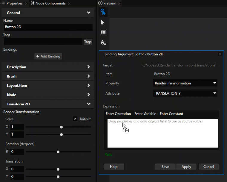
When you write expressions for bindings in the Binding Argument Editor, the fastest and most accurate way to add nodes and their properties to an expression is to drag them from the Properties to the Expression editor in the Binding Argument Editor.
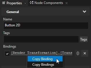
Add more bindings to the same node. For example:
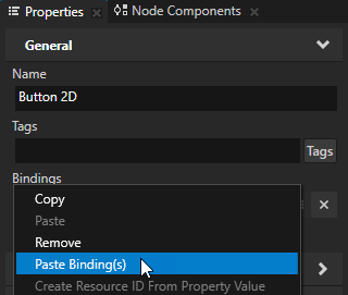
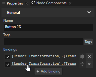
In the Properties right-click the existing binding, select Copy Binding, right-click the Bindings property, and select Paste Binding(s).
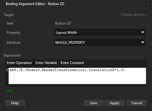
To edit the binding that you pasted in the previous step, in the Properties click the binding and in the Binding Argument Editor set Property to Layout Width. You bind the width of the node to the same value as the Render Transformation property Translation Y property field.
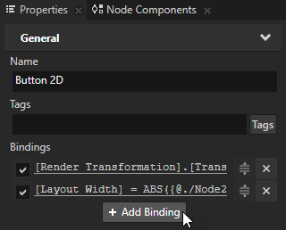
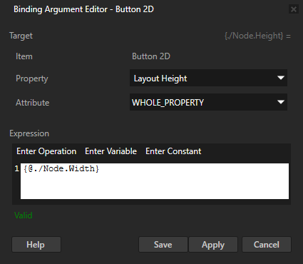
In the Properties click + Add Binding, and in the Binding Argument Editor set:
Property to Layout Height
Expression to
{@./Node.Width}
You bind the height of the node to the width of the node to keep the button square-shaped.
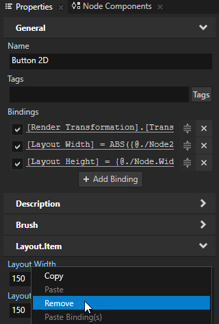
In the Properties right-click the Layout Width and Layout Height properties, and select Remove. You can remove the Layout Width and Layout Height properties because bindings control those properties. The properties you bind override the properties set in the Properties.
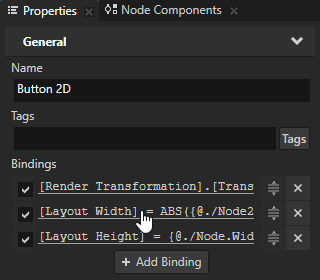
In the Properties click the Layout Width binding to edit it, and in the Binding Argument Editor set Expression to
You set the initial size of the button to be 50 by 50 pixels.
When you move the button on the x axis, the button changes size and position on the y axis.
Binding to the properties of other nodes
You can bind properties and property fields of one node to those of other nodes.
To bind to the properties of other nodes:
In the Project create or select the node to the properties of which you want to bind.
For example, create a Button 2D node and in the Properties add and set:
Background Brush to a Color Brush, Texture Brush, or Material Brush that you use to fill the Button 2D node. See Adjusting the appearance of 2D nodes.
Horizontal Alignment and Vertical Alignment to Center
Layout Width and Layout Height to set the size of the button
Render Transformation You use this property later in this procedure to set the position of the button.
Create another node and bind one of its properties to a property of the node that you created in the previous step. For example:
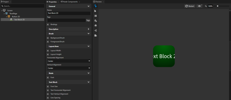
In the Projectpress Alt and right-click the node that you created, select Text Block 2D, and in the Properties add and set the Horizontal Alignment and Vertical Alignment properties to Center.
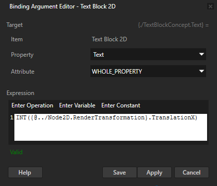
In the Properties add the Bindings property and in the Binding Argument Editor set:
You bind the Text property of the node to the Render Transformation property Translation X property field of its parent node, and convert the value to an integer.
When you change the value of the Render Transformation property Translation X property field of the node that you created in the first step of the procedure, the text in the Text Block 2D node changes to show the current position of the node on the x axis.
Creating a more complex binding
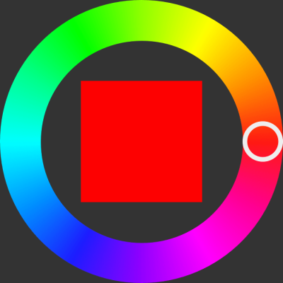
A more complex binding involves binding properties of one node to properties of other nodes and using several variables and functions. In this example, you create a color wheel with a slider that sets the color of a color swatch.
To create a more complex binding:
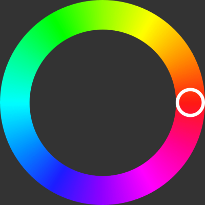
Create a node that contains a slider whose ring-shaped knob moves along a color wheel: For example:
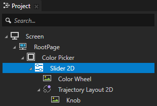
In the Project create an Empty Node 2D node and inside the Empty Node 2D create a Slider 2D node with this structure:
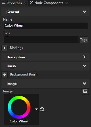
An Image node that shows the color wheel and visually represents the rail along which the slider knob moves.
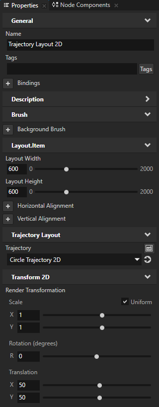
A Trajectory Layout 2D node that acts as the rail along which you want to move the slider knob and in the Properties add and set:
Layout Width and Layout Height to 600
Render TransformationTranslationX and Y property fields to 50
This way you position the trajectory layout over the color wheel.
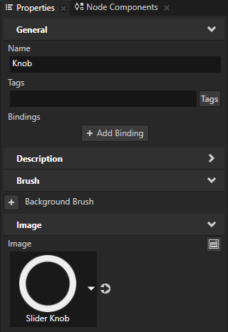
Inside the Trajectory Layout 2D create an Image node that you want to use as the visual representation of the slider knob.
TIP
To see the trajectory, in the Preview click to enter the Analyze mode, right-click , and select Debug objects.
In the Project select the Slider 2D node and in the Properties add and set the Layout Height and Layout Width properties to 700.
In the Project select the Trajectory Layout 2D node, in the Properties next to the Trajectory property click to go to that resource and set:
Radius to 300 You set the radius of the trajectory to half of the width of the Trajectory Layout 2D node.
Angle to 180 You set the starting point of the trajectory to the color red, the hue of which is 0.
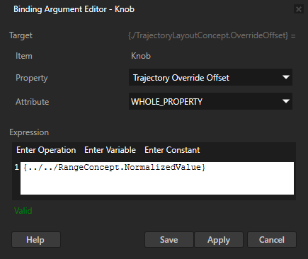
In the Project select the Knob node, in the Properties add the Bindings property, and in the Binding Argument Editor set:
Property to Trajectory Override Offset
Expression to
{../../RangeConcept.NormalizedValue}
Click Save.
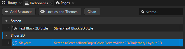
In the Project select the Slider 2D node and in the Dictionaries:
Click + Create Resource Dictionary and select the Slider 2D resource dictionary you created.
Click + Add Resource, select Create > Alias, name the alias $layout, and set it to point to the Trajectory Layout 2D node that the Slider 2D node uses as a rail. Kanzi uses this alias to tell the slider along which trajectory to move the slider knob.
Create a swatch that shows the currently selected color:
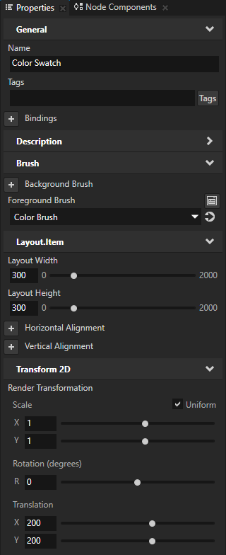
In the Project in the Empty Node 2D node that you created in the first step create an Empty Node 2D node and in the Properties add and set:
Layout Width and Layout Height to 300 This way you set the size of the swatch.
Foreground Brush, select + Color Brush, click next to the property, and set Brush Color to red. You set the color of the Color Brush to the color that is initially selected in the color wheel.
Render TransformationTranslationX and Y property fields to 200 You position the swatch inside the color wheel.
You use this node to show the color that the user selects in the color wheel with the slider that you created in the previous step.
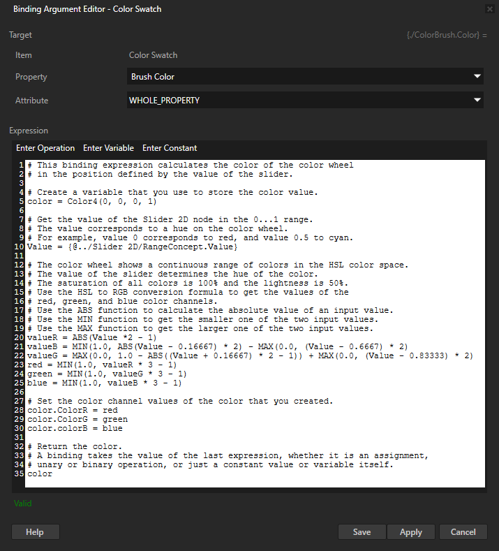
In the Prefabs select the Empty Node 2D node that shows the color swatch, in the Properties click + Add Binding, and in the Binding Argument Editor set:
Property to Brush Color
Expression to
# This binding expression calculates the color of the color wheel
# in the position defined by the value of the slider.

# Create a variable that you use to store the color value.
color = Color4(0, 0, 0, 1)

# Get the value of the Slider 2D node in the 0...1 range.
# The value corresponds to a hue on the color wheel.
# For example, value 0 corresponds to red, and value 0.5 to cyan.
Value = {@../Slider 2D/RangeConcept.Value}

# The color wheel shows a continuous range of colors in the HSL color space.
# The value of the slider determines the hue of the color.
# The saturation of all colors is 100% and the lightness is 50%.
# Use the HSL to RGB conversion formula to get the values of the
# red, green, and blue color channels.
# Use the ABS function to calculate the absolute value of an input value.
# Use the MIN function to get the smaller one of the two input values.
# Use the MAX function to get the larger one of the two input values.
valueR = ABS(Value *2 - 1)
valueB = MIN(1.0, ABS(Value - 0.16667) * 2) - MAX(0.0, (Value - 0.6667) * 2)
valueG = MAX(0.0, 1.0 - ABS((Value + 0.16667) * 2 - 1)) + MAX(0.0, (Value - 0.83333) * 2)
red = MIN(1.0, valueR * 3 - 1)
green = MIN(1.0, valueG * 3 - 1)
blue = MIN(1.0, valueB * 3 - 1)

# Set the color channel values of the color that you created.
color.ColorR = red
color.ColorG = green
color.colorB = blue

# Return the color.
# A binding takes the value of the last expression, whether it is an assignment,
# unary or binary operation, or just a constant value or variable itself.
color
Click Save. You bind the value of the Brush Color property to a color value that you calculate based on the Value property of the Slider 2D node. You can bind the Brush Color property of a node that has either the Foreground Brush or the Background Brush property but not both properties. If the node has both Background Brush and Foreground Brush properties, Kanzi Studio does not know to which of the two brushes you want to bind.
In the Preview when you drag the knob along the color wheel the color swatch shows the color under the knob.
Using bindings to customize instances of a prefab
A prefab can contain a tree of nodes, each with their own properties. When you edit the nodes in a prefab or any of its instances in a project, you change those nodes in all instances of that prefab. However, you can customize individual instances of the prefab to have individual values by overriding the values in the default prefab. For example, when you create a prefab for an address book entry you want to show a different name, number, and photo for each address book entry.
To customize individual instances of a prefab:
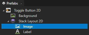
In the Prefabs select the node in a prefab you want to customize in an individual instance of that prefab.
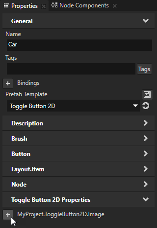
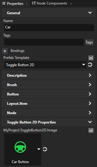
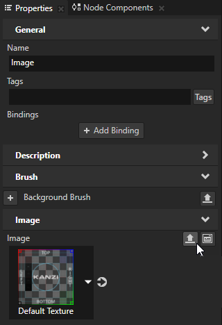
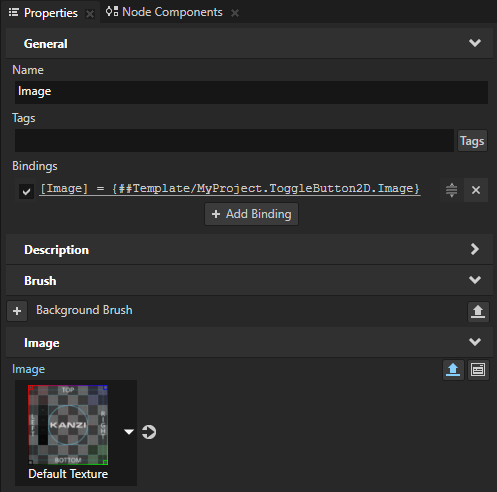
In the Properties next to the property you want to edit click . Kanzi Studio creates from that property a custom property, adds it to the root of the prefab, and creates a ##Template binding to the property in the prefab root. See Prefab root bindings.
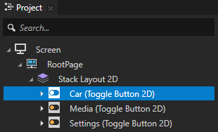
In the Project select the root of the prefab instance you want to customize.
In the Properties click next to the property for which you enabled editing and select the resource or enter the value of the property you want to use only in that instance of the prefab.
Using piecewise functions in bindings
You can use the Animate binding function to set how a value of a property changes using a piecewise function. For example, you can use the Animate function to set the needle in a gauge to move faster between values 0 and 100 than it does for values larger than 100. See Animate.
To use a piecewise function in a binding:
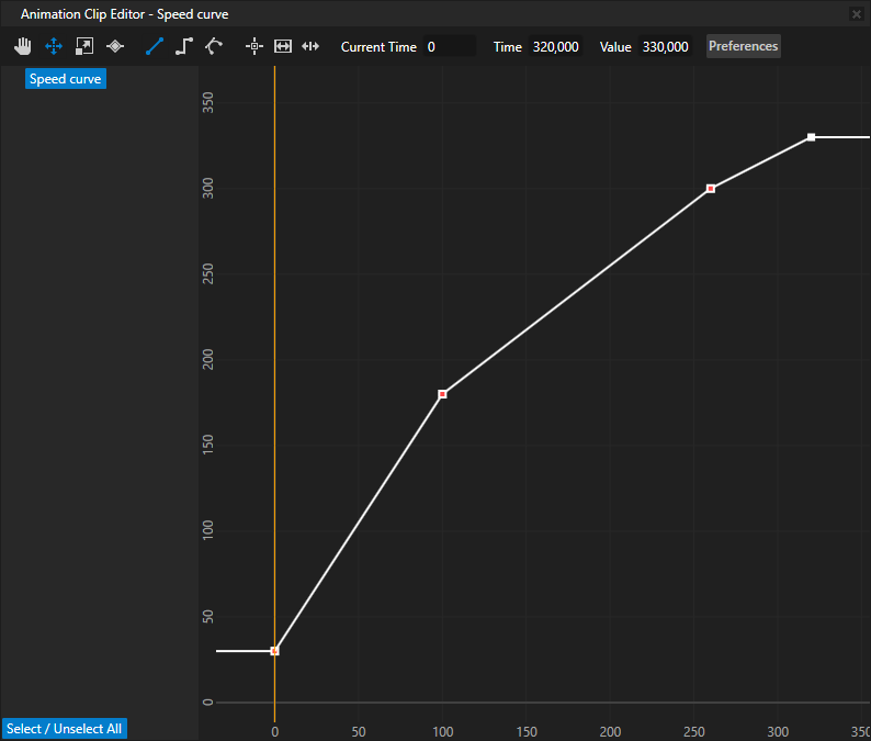
Create an Animation Data item. See Animations. For example, create an Animation Data item named Speed curve that contains four keyframe points which define three different segments. Create keyframes at:
Time 0 with Value 30
Time 100 with Value 180
Time 260 with Value 300
Time 320 with Value 330
You use these keyframes to set the rotation of a speed needle at different speeds. For example, when the speed is 100, you set the rotation of the needle to be 180 degrees.
In the Project select or create a node for the properties of which you want to use the piecewise function you created in the Animation Data item in the previous step. For example, to create a speed needle create an Empty Node 3D node, name it Speed Needle, add to it a Model node which shows a speed needle, and position the Model so that you can use the Empty Node 3D to rotate the Model around a desired point along the needle. See Editing the origin of nodes.
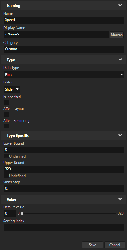
In the Library > Property Types create the property type you use to control the position of the needle. For example, create a property type named Speed and set the Upper Bound property to 320. When you create a property type, Kanzi Studio by default creates a custom float property type with a slider editor.
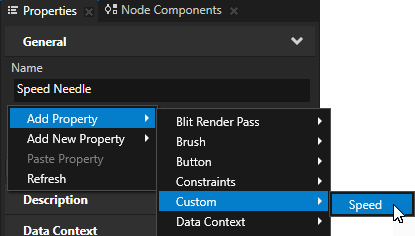
In the Project select the Empty Node 3D node which represents the speed needle and in the Properties add the property type that you created in the previous step.
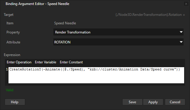
In the Properties add the Bindings property and in the Binding Argument Editor set:
Property and Attribute to the property and property field you want to use to position the speed needle with the expression in the binding. For example, set:
Property to Render Transformation
Attribute to Rotation Create a binding for each attribute you want to animate.
Expression to the expression that animates the change in the position of the speed needle using a piecewise function. Use the Animate function to bind the property type that you use to control the position of the needle to the piecewise function you define in the Animation Data item you created in the first step. See Animate. To point to the Animation Data item use either:
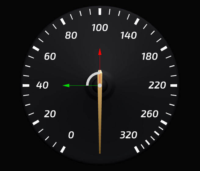
When you change the value of the Speed property in the Speed Needle node the needle moves. The piecewise function you define in the Animation Data item Speed curve sets the rotation of the needle. The needle moves in:
Largest increments when the value of the Speed property is between 0 and 100
Smaller increments when the value of the Speed property is between 100 and 260
Smallest increments when the value of the Speed property is between 260 and 320
Creating dynamic kzb URLs with bindings
You can create the kzb URL of a resource in your project dynamically in a binding expression. For example, you can create a binding which creates the kzb URL of a texture based on data from a data source and sets an image in your application to use that texture.
For example, to create a binding which dynamically creates the kzb URL of a texture:
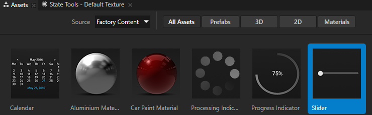
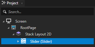
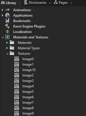
In the Project create or select a node whose property type you want to use as input for creating the kzb URL of a resource in your project. You can also use a custom property type or a data source. See Creating property types and Using a data source. For example, use the Slider from the Factory Content to dynamically create the kzb URL of a texture in your project based on the value of that slider. See Using the Factory Content assets. If your project contains textures called Image0 to Image10, you set the Image property of an Image node to one of those textures based on the value of the slider. For example, when the value of the slider is 5.0, you set the Image property to the Image5 texture.
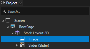
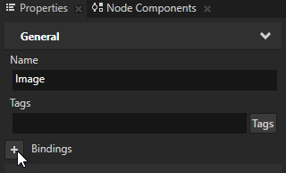
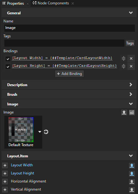
In the Project create or select a node whose property you want to bind to the dynamically created kzb URL and in the Properties add the Bindings property. For example, create an Image node and add the Bindings property to that node.
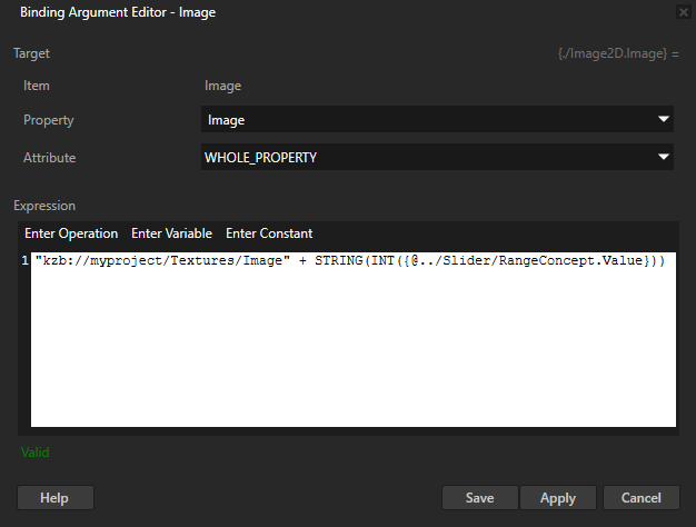
In the Binding Argument Editor set:
Property to the property that you want to bind to a dynamic kzb URL. For example, set it to Image.
Expression to the binding expression where you create the kzb URL to a resource in your project. For example, if you set the Property to Image, use an expression which creates the kzb URL of a texture based on the value of the slider that you created in the first step.
Click Save. You bind the value of the Image property to the static part of the kzb URL, which points to the textures in your project, and the dynamic part, which comes from the slider. Before you can concatenate the two parts, you must cast the float value that comes from the slider to an integer and then convert it to a string. When you change the value of the slider, the value of the Image property changes too.
TIP
To get the kzb URL of a resource, in the Library right-click the resource and select Copy .kzb URL.
In the Preview when you move the slider knob, the texture that the Image node shows changes based on the value of the slider.
Using bindings as an alternative to property inheritance
You can use bindings as an alternative to property inheritance. You can use property inheritance for defining a property in a parent so that it is inherited by a child node, but it works only when a property is inheritable and it is acceptable to have the property inherited by all child nodes. See Property system.
To use bindings as an alternative to inheritance:
Create a custom property and add it to the node to which you want to create a binding.
In the Project select the node to which you want to add a binding and in the Properties add the Bindings property.
In the Binding Argument Editor set:
Property and Attribute to the property and attribute you want to bind.
In the Expression editor enter the expression to include the custom property you created in the beginning of this procedure.


 to enter the Analyze mode, right-click
  , and select Debug objects.
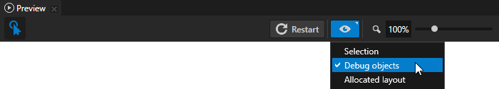

 to go to that resource and set:
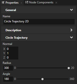
 next to the property, and set Brush Color to red.
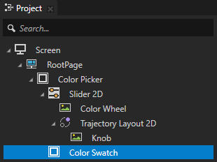
 .
.
 next to the property for which you enabled editing and select the resource or enter the value of the property you want to use only in that instance of the prefab.